基于PCM2702的USB声卡原理图及电路图
了解电路图的读法,能看懂原理图和接线图 #生活知识# #生活技能# #基础电工#
基于PCM2702的USB声卡原理图及电路图
Make a sound card is no more a complex issue. If you use great IC PCM2702 from BURR BROWN / Texas Instruments you can create a fully functional USB sound card. This sound card can be powered from USB port and has one stereo output. You don’t need to install any driver for Windows XP and Vista, because they are already inside. This is really plug and play.
Few months ago I have seen USB sound card called Alien DAC. The construction on the project web page inspired me to build this thing also.
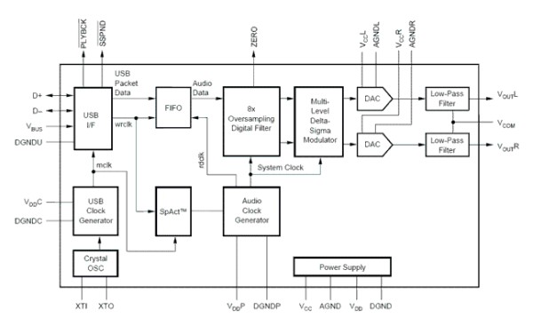
The core of this construction is 16-Bit Stereo Digital-To-Analog Convertor with USB interface PCM2702.
PCM2702 needs only few additional parts to work. The schematic is not complex. Sound card can be powered directly from USB port (jumper W1) or from external power supply (jumper W3). PCM2702 needs two power supply 3.3V (3V-3.6V) and 5V (4.5V-5.5V). I used fixed output voltage LDO TPS76733Q for 3.3V (IO2) and adjustable output voltage LDO TPS76701Q for 5V (IO3). Both LDO are produced by TI, I used this because I had it in my drawer. Any similar LDO can be used. Output voltage of IO3 should be set to little bit lower than input voltage to allow LDO good stabilization, in my case output voltage is set to 4.8V. Output voltage can be set by adjustable resistor R33. In case of low power supply, IO3 can be shorted by jumper W3. LED D3 signalizes power on.
Small ferrite beads are placed before all power pins of PCM2702 and in Vbus and GND of USB. These small beads reduce high frequency hum. I had a problem find this small SMD ferrite beads in local stores but finally I acquire few of them from old hard drive. They are not absolutely necessary, you can use zero ohm resistors instead of them.
Low-pass filter is placed in output signal path to reduce sampling frequency. An OPA2353UA dual op amp is configured as a stereo 2nd-order low-pass filter. Led diode D1 is illuminated when PCM2702 plays audio data received from the USB bus. Led diode D2 is illuminated when USB bus suspends audio data transmission to the PCM2702.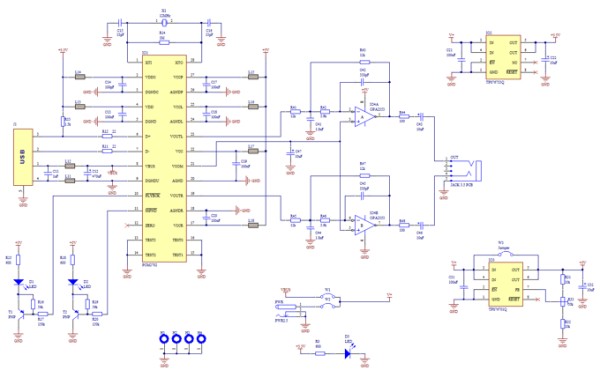
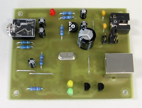
PCB图:
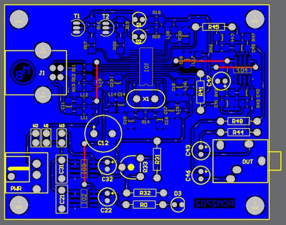
PCB assembly diagram
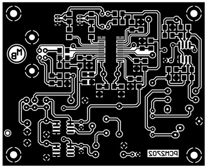
PCB - Download PCB in [EPS format] or [PDF format]
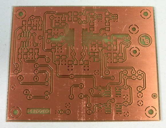
Bottom side of PCB (single side PCB, made by standard etching method)
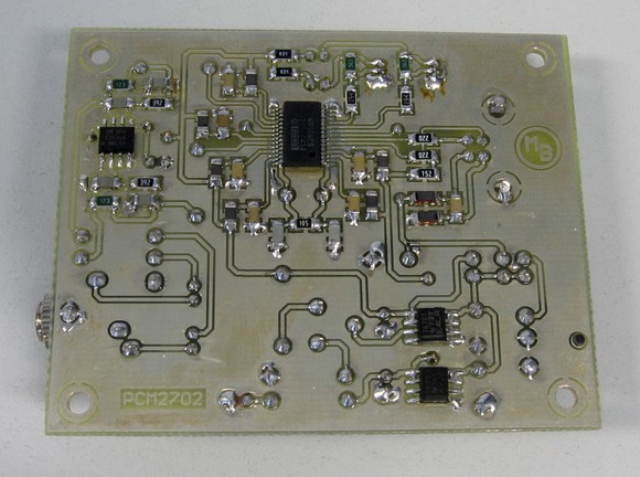
Assembled bottom side
Conclusion
This circuit works very well. I only shorted crystal during soldering so the circuit didn’t work, but after removing the short the sound card started to work. I have tested in Windows 2000, XP and Vista. It works in all mentioned systems. Drivers are present in operation system so the sound card is ready in few seconds after you connect it.
During writing this article I have found that PCM2702 is now not recommended for new design, but TI offer even better solution. PCM2704, PCM2705 have same functionality as PCM2702, but they include output filter. They are able to drive directly headphones. Volume and Mute can be controlled through SPI bus in PCM2705 or with pushbuttons in case of PCM2704. PCM2704 and PCM2705 are in TSSOP28 package. PCM2706 is similar to PCM2704 and PCM2707 to PCM2705 but in addition they have I2S bus. PCM2706 and PCM2707 are in TQFP32 package. I recommend using these new chips for new design (look at the TI web page).
关键字:PCM2702 USB声卡引用地址:基于PCM2702的USB声卡原理图及电路图声明:本文内容及配图由平台用户或入驻媒体撰写。文章观点仅代表作者本人,不代表EEWorld网站立场。文章及其配图仅供工程师学习之用,如有内容侵权或违规,请联系本站处理,邮箱地址:bbs_service@eeworld.com.cn
上一篇:自动点烟器电路原理
下一篇:美的家用全自动洗碗机电路图
网址:基于PCM2702的USB声卡原理图及电路图 https://www.yuejiaxmz.com/news/view/874563
相关内容
基于STM32的水质监测系统设计与实现:硬件电路、软件程序和原理图详解,基于STM32的水质监测系统:原理图、仿真图、板图、源码全解析USB设备能否传输声音信号?全面解析USB音频传输功能
USB
SS8050,SS8050 pdf中文资料,SS8050引脚图,SS8050电路
【图】2017换代款H6出厂原版及CarLife车机(多媒体)固件下载及说明
【微波炉原理】微波炉的工作原理图解 微波炉的电路图分析
宾馆酒店插卡取电原理图解
整理你的办公桌面,仓华 USB
微波炉原理与维修(含电路图).doc
基于LabVIEW的智能厨房助手机器人
随便看看
最新动态分享
- 厨房与卫生间一体化设计,打造精致生活的全新趋势
- 懂生活的业主都这样做:厨卫“去家务化”,生活不要太轻松
- 老房子厨房卫生间改造
- 装修必看!厨卫这几个关键位置升级后,生活品质直线上升!
- 厨房装修布局尺寸全解析:10个实用方案,金牌设计师精确到厘米!
- 现代住宅建筑空间组合设计
- 42 ㎡ 法式奶油风 loft,打造年轻人的梦幻生活室内装修设计、装修效果图
- 卫生间越来越流行这么装,漂亮实用幸福超强,你家最多叫厕所
- 标准化卫生间和厨房设计,这些地方不能出错!
- 厨房和洗澡间怎么设计 厨房和卫生间怎样布局才最合理
热点动态分享
- 3179
- 2932
- 2923
- 2676
- 2513
- 1972
- 1695
- 1612
- 1598
- 1513